What is Multi Jet Fusion (MJF) 3D Printing?
In this guide, we’ll provide insights into MJF 3D printing benefits, applications, design tips, and more.
What is Multi Jet Fusion (MJF)?
How does the MJF process work?
- The MJF 3D printing process begins with a thin layer of powder material spread across the build platform.
- The print head applies a fusing agent to areas to be solidified and a detailing agent to define edges.
- A heat lamp heats the layer, causing the fused areas to bond and form the part.
- The build plate lowers and the process repeats layer-by-layer until the part is complete.
MJF Specifications
Measurement | Specification | |||
|---|---|---|---|---|
Build Volume | 15 x 11.2 x 15 in (380 x 284 x 380 mm) | |||
Build Speed | Up to 5058 cm3/hr (309 in3/hr) | |||
Layer Thickness | 0.08 mm (0.003 in) | |||
Tolerances | +/- 0.012 in. (0.30mm) plus 0.1% of nominal length | |||
Warpage | We recommend maintaining a uniform thickness of 0.125 in. (3.175mm) to ensure stability |
MJF Advantages
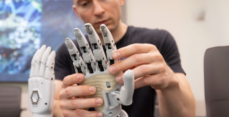
- High Precision and Detail
MJF ensures excellent surface quality and intricate detailing, achieving layer thicknesses as fine as 80 microns and dimensional tolerances within ±0.012 in., ensuring high accuracy. Its isotropic mechanical properties mean that parts produced with MJF are strong in every direction. This is particularly important when creating complex parts that require durable small features.

3D-printed camera lenses printed with Nylon PA 11. Source: HP
- Consistent Quality
MJF delivers a consistent repeatability of ±0.3% across builds, ensuring reliable and repeatable results. This consistency is crucial when dealing with varying batch sizes or complexities of parts. With this level of repeatability, manufacturers can ensure uniformity across thousands of parts or for production runs that require exact replacements for end-use components.
- Fast Production Speed
With high throughput, MJF 3D printing can produce parts up to 10X faster than SLS 3D printing, making it ideal for rapid manufacturing and serial production. Unlike Selective Laser Sintering (SLS) which traces each cross-section individually by laser, MJF 3D printing simultaneously prints entire layers and has a linear fusing process.
- Efficient Material Usage
MJF 3D printing utilizes up to 80% of the material, significantly reducing waste and making it a cost-effective solution. This high material efficiency is achieved by recycling unused powder from the printing process.
Depowdeirng an MJF part at a processing station
- No Supports Needed
MJF eliminates the need for supports during the printing process, giving designers greater flexibility to create complex geometries. This capability enables the production of highly detailed shapes including interlocking parts, hollow structures, and intricate lattice designs.
Furthermore, manufacturers can streamline the post-processing phase by eliminating the need to remove support structures. This not only shortens the overall production timelines but also enhances surface quality by maintaining a smooth finish without the marks often left by traditional support structures.
What material does MJF use?
Here is the list of MJF 3D Printing materials available at Endeavor 3D:
Material | Description | Common Applications |
|---|---|---|
HP Nylon PA 12 is a versatile 3D printing material known for its high strength, dimensional stability, and low moisture absorption, making it ideal for creating precise, durable parts. This material offers exceptional surface quality. | Watertight applications, housing and enclosures, spares and repairs, functional prototypes, medical devices, jigs and fixtures | |
HP Nylon PA 12 FR is a flame-retardant, halogen-free material with 60% powder reusability and a smooth surface finish. This material meets UL94 V0 flammability standards at 2.5mm thickness. | Electrical components, fluidic systems, robotics, and machinery parts | |
HP Nylon PA 12 S is a high-performance, eco-friendly material offering exceptional surface finish, high reusability (up to 85%), and cost-effective production with up to 25% reduction in variable costs per part. | Lighting, aesthetic covers, orthotics and prosthetics, volume prototyping, dental molds, jigs and fixtures | |
HP Nylon PA 12 White is a high-density, fine-feature resolution material that’s easy to color and dye in post-processing, making it ideal for durable, customizable prototypes and end-use parts. | Prosthetics, orthotics, household appliances, biocompatible parts, prototypes, consumer products | |
| Fuel lines, air brake tubing, pneumatic tubing, hydraulic hoses, functional protyping, sports gear, industrial tooling and jigs | |
ULTRASINT® TPU01 offers exceptional flexibility, resilience, and durability, making it perfect for applications requiring high abrasion resistance and elasticity. This versatile material supports complex geometries and provides excellent impact absorption. | Orthotics and prosthetics, car hose and tubes, bike seats, footwear, sporting equipment, protective casing |
MJF Post Processing Options
Initial Processing
- Cooling:
Once printing is complete, MJF parts need time to cool down within the build chamber. MJF utilizes a standalone cooling process, reducing the temperature gradients that cause internal stresses relating to shrinkage and warpage. Furthermore, this cooling technique allows the build unit to be used for a new print without waiting for the part to cool.
- Depowdering:
After cooling, the parts are removed from the chamber and undergo depowdering to clear away excess powder. This step is typically performed with specialized tools and high-pressure compressed air.
- Bead Blasting:
To refine the part’s surface texture, bead blasting is applied. This process removes any excess loose powder particles and smooths out any remaining rough areas.

DyeMansion bead blasting station
Secondary Post Processing
- Vapor Smoothing:
Applying vapor smoothing to an MJF part creates a smooth, glossy finish. The process seals tiny pores and surface inconsistencies allowing the part to withstand moisture while enhancing the durability.
- Tumble Smoothing:
High-energy tumble finishing uses small media and high forces to provide the deburring and polishing of MJF parts with intricate grooves and corners.
- Coloring and Dyeing:
Typically beginning with a natural grey base, MJF parts can be dyed into a variety of colors. At Endeavor 3D, we use a combination of DyeMansion deep-dyeing techniques and our in-house custom coloring to create long-lasting, consistent colors.
One standout option for achieving vibrant, lasting colors is PA 12 White. Unlike the standard grey base, PA 12 White provides an excellent foundation for dyeing, as it absorbs pigments more effectively, resulting in brighter and more saturated hues. This material’s biocompatibility and low-moisture absorption make it ideal for applications like prosthetics and orthotics, consumer goods, and household appliances.
For more information, download our advanced finishing and custom coloring capabilities document.
Leveraging design to save costs with MJF 3D Printing
- Part Consolidation:
Part consolidation can replace complex and expensive components while driving performance improvements. This technique can reduce costs significantly by eliminating the need for capital investments in tooling. Furthermore, part consolidation allows engineers to make quick modifications for part performance.
In the example below, an injection-molded air duct that originally had 14 parts was scanned and printed into a single part using Multi Jet Fusion. By using both MJF and part consolidations, the presence of seams across the part was eliminated, improving airflow. The total cost to produce the part was reduced by over 30%, with $190,000 in capital expense being avoided. Furthermore, the time it took to assemble the parts was eliminated, helping streamline the production process.

Injection molded air duct

3D printed air duct
- Build Packing:
The approach to build packing in the design phase is critical to maximizing throughput and efficiency in MJF 3D printing. Efficiently packed build boxes not only shorten print times but also lower material costs. To leverage this capability, designers must analyze the types and orientations of parts entering the build box. For optimal packing density, it’s essential to consider each part’s geometry, as parts with complex or variable geometries often nest better than simple, uniform shapes.
At Endeavor 3D, we have three main build packing orientations that determine the level of quality, cost, and total parts produced during the printing process. Below we showcase the three nesting options for an end-of-arm tool made from Nylon PA 12 with dimensions of 47.5 x 41.3 x 92.5 mm:

Three MJF 3D printing build box nesting options
When determining part orientation, consider that MJF 3D printing does not require support structures. This enables greater flexibility in how parts are arranged, as they can be stacked and angled without risking print quality. However, engineers need to factor in part spacing to manage thermal stresses. Parts packed too closely together can lead to localized overheating and unwanted fusing of parts.
- Hollowing:
For non-structural parts or applications where internal solidity isn’t necessary, hollowing out the part can reduce material use and production costs. Hollow designs and internal cavities reduce the powder material needed without compromising the part’s outer strength. This can also allow for lighter parts for end-use applications which is a significant benefit for fields like aerospace and automotive.
Similar to hollowing out a part for end-use parts, designers can reduce post-processing time and increase yield by designing release holes or sacrificial features. This is intended to remove powder more efficiently during the depowdering phase. For example, augers, a sacrificial component, can be used to remove powder from long thin channels.

Sacrificial auger component for powder removal
MJF Design Tips
1. Feature Size for Fine Details
- The recommended minimum thickness for short walls oriented on the XXY plane is 0.3 mm, and 0.5 mm for short walls oriented in the Z direction.
- Raised text, logos, or engravings should be at least 1 mm tall to be visible.

2. Clearance for Moving Parts and Assemblies
- Designing clearances for moving parts is essential to prevent fusing and ensure functionality. For parts with walls thinner than 3 mm, the clearance between faces should be more than 5 mm, allowing them to move freely after printing. For most assembly parts being printed together, the clearance between part faces should be a minimum of 0.7 mm to prevent friction or interference.
- Note: It’s advisable to test clearances on a smaller scale before committing to larger builds, as different geometries may have varying shrinkage or tolerances.
3. Overhangs and Support-Free Geometry
- One of MJF’s major advantages is its ability to print without supports, thanks to the powder-bed fusion process. However, overhangs sharper than 45 degrees may experience some sagging, so it’s best to maintain angles above 45 degrees wherever possible.
- Using chamfers or radii on overhangs and edges can reduce stress concentrations, aiding in both structural stability and aesthetic finish. Designs with angles closer to 30 degrees require careful consideration to ensure they can handle thermal stresses and layer adhesion without warping.
4. Infill Strategies and Weight Reduction
- For hollow designs, the minimum recommended diameter of escape holes is 5 mm. There should be at 2 of them to allow compressed air depowdering.
- Incorporating honeycomb or grid patterns can also help maintain structural integrity while reducing weight. MJF’s precision allows for detailed lattice designs, but walls surrounding these infill patterns should still adhere to the minimum thickness guidelines to prevent collapse or powder retention.

5. Thermal Considerations for Consistent Part Quality
- MJF printing uses high temperatures, and variations in thermal exposure can lead to part inconsistencies or surface blemishes. To mitigate this, aim to avoid large solid sections or abrupt shifts in thickness, as these can cause uneven heat distribution and lead to warping or sink marks.
The value of a reliable MJF Part Supplier
Partnering with a contract manufacturer like Endeavor 3D offers clear advantages for lowering upfront costs. By outsourcing MJF production, companies can avoid significant capital investment associated with purchasing and maintaining high-end MJF 3D printing equipment. This gives our customers the advantage of scaling production without the burden of additional expenses.
Endeavor 3D is a dedicated MJF manufacturing partner, offering product design, production, quality assurance, 3D scanning, reverse engineering, post-processing, and fulfillment services. Our commitment to quality and precision is demonstrated by our ISO 9001:2015 certification, ITAR registration, and status as an HP Digital Manufacturing Partner. With our team’s expertise and advanced technology, we ensure your MJF parts are produced efficiently, accurately, and ready for use in even the most demanding applications. Contact a 3D printing expert to learn more about how MJF 3D printing can benefit your project.