What is Design for Additive Manufacturing (DfAM)?
The remaining challenge lies in the relative novelty of the technology. While engineers today generally understand the basics of 3D printing, there is still a significant gap in universal knowledge of the necessary design criteria. In contrast, injection molding benefits from well-established design optimization courses and advanced software systems like MoldFlow analysis, which help ensure part success. For additive manufacturing, design principles are gradually becoming more standardized and aligned with improvements in machine reliability.
Design for Additive Manufacturing - the key to successful 3D printed products

Because each 3D printing technology operates differently, the DfAM principles discussed here are tailored specifically to powder-based manufacturing, with a particular focus on HP Multi Jet Fusion technology. Developed by Hewlett Packard, a leader in consumer and industrial printing,
Using DfAM to ensure first-round success for MJF products

These initial design for additive manufacturing guidelines help set the design expectations at the outset of the product development process to ensure that the selected item has the maximum chance of success before being produced by a contract manufacturer like Endeavor 3D. Understanding these principles is also a key communication tool internally for other design engineers, product owners, management teams, or end-customers to eliminate surprises or delays. When these core principles are in place from part selection to design approval, then the risk is almost fully removed from production.
The graph above illustrates several key business advantages of 3D printing. First, it significantly reduces product development costs by enabling multiple design iterations to be tested simultaneously during each phase. Second, it accelerates time-to-market by eliminating the need for injection molding or vacuum casting tooling, allowing for turnaround times as quick as 5–7 days. Without tooling constraints, designers and engineers can easily and cost-effectively update designs at any stage of the product lifecycle. Additionally, advancements in 3D printing machines and materials enable the production of parts suitable for end-use applications, delivering immediate value to your organization.
")
The Basics: 5 Quick Wins Using Design for Additive Manufacturing (DfAM)
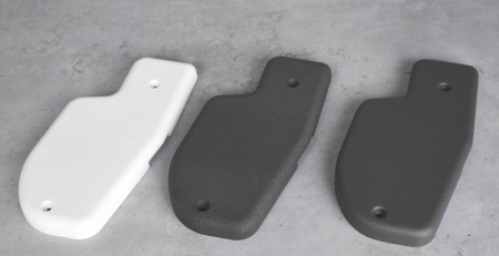
- Strong, Functional Parts: HP MJF is ideal for producing durable components like brackets, casings, and covers.
- Optimal Part Size: Best results are achieved with small to medium-sized parts (5–25 mm) that have a compact form.
- Complex Geometries: The more intricate the geometry, the greater the advantage of 3D printing, as traditional tooling costs rise disproportionately with complexity.
- Moderate Detail Resolution: Parts should avoid extremely fine details, targeting a minimum feature size of 0.3 mm.
- Production Volumes: MJF is most efficient for mid-sized parts in quantities of 5–500 and smaller components in runs of 1,000–5,000.
By keeping these considerations in mind, you can maximize the benefits of HP MJF for your designs.

1. Proper use of Wall Thickness in MJF
The process of fusing layers in HP Multi Jet Fusion relies on a baseline wall thickness of 3mm in the X-Y and 5mm in the Z direction of the design to guarantee strength. Smaller dimensions are possible but often require a “calibration print” to ensure a good output. Smaller features are also potential fail-points so when aiming towards series products it is important to land in the middle of the tolerance spectrum.

More information about ensuring accuracy using design for additive manufacturing is in the sixth part of this series.
2. DfAM Tolerance Requirements for MJF
Typically, a part prepared for Multi Jet Fusion using principles of design for additive manufacturing can expect to meet IT Grade 13 accuracy (DIN 16742 TG6 – TG7 ) standards for part manufacturing. The highest accuracy is always on the X-Y plane because that is where the print head is depositing the bonding agent. Critical features should always be placed in that orientation. In the best cases, they are also noted in advance to ensure that the in-house production or an external printing service can optimize for those features when preparing production.
Tighter tolerances are achievable using scaling of particular features within a design. This requires close communication with the production team to ensure that the expectations are clearly defined and taken into account. Typically, 1-3 iterations would be produced with slightly different scaling factors to reach the optimal fit for series production. In some cases, you can get to a level of 0.15 mm for select features after accounting for placement within the machine.
The guidelines in the Ensuring Accuracy Article provide an excellent approach to improving performance.
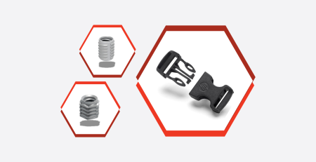
3. Designing for Snap Fits and Inserts in MJF

Working with snap fits there are a few basic design rules to follow to engineer
The second rule is that depending on where accuracy is most critical, the part should be printed in a different orientation. The critical geometry should be on the X-Y plane and that should be communicated to the production floor. A third consideration is that fusing plastic is slightly less stable than full-injection molded material. The difference is not as dramatic as other processes, but particularly if the snap is thin, a performance test should be used to validate the design. Some rules of thumb for calculating the strength are in the detailed guidelines.

For applications that do not require regularly removing and reinserting the connecting part, 3D-printed threads can be designed directly. The main factor is the resolution of the threads which need to be produced. 3D printing is particularly interesting for large, non-standard thread types where one-off cutting tools can easily run in the thousands of euros and be relatively inconsistent in placement compared to 3D printing. For standard sizes of screw threads, the shape can be cut directly into the part like any other plastic.
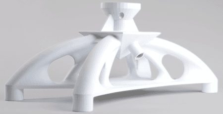
4. Designing Interlocked Moving Elements using MJF
One of the more interesting advantages of 3D printing is designing fully articulating parts directly from the 3D printer. The basic principle is that a hinge element or moving ball joint is added to the original design file as a fully enclosed system. There is then an opening at the bottom or front of the design so that the unfused powder falls out of the moving joint after a minimal amount of use. The part then has a secure joint without requiring any additional hardware.

More ideas for optimizing parts with interlocked elements can be found in the article on assembly consolidation.
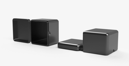
5. Joining Rules for Oversized Parts in MJF

Successfully joining parts and achieving structural strength comes from two steps. First, the design for additive manufacturing principles for accuracy and tolerances needs to be used while preparing the interlocking joining areas. This ensures that the design has slight tolerances so it will fit properly while still having a tight fit. It is also important that the parts that will connect are printed in the same orientation so that any process deviations occur to both pieces equally. The second step is using a time-tested joining method to work with larger surface areas for gluing to ensure the strength of the connection. This means, there is not a straight cut, but instead, teeth, corners or ledges that provide structural strength similar to traditional woodworking designs. In fact, our experience is that when the part uses design for additive manufacturing principles, any part breakage due to impact or weight overload will occur somewhere else on the part since the engineered joint with bonding through glue is particularly robust. We have many additional tips and examples in the detailed article on designing for accuracy.
Capturing Early Wins Using Design for Additive Manufacturing
When these“quick win” applications have won acceptance within your organization, the next step is to add specialty functionality and design elements that are unique to additive manufacturing. This will help you gain a competitive market advantage alongside the pure business advantages from the quick wins. Those DfAM features have a more difficult learning curve in the initial design phase but remove processing steps later in the value chain or unlock strong performance advantages for your products.
The pathway is clear. When will you pick up your 3D-printed quick win?