Handbook for 3D Printing Assembly Consolidation with DfAM
Our overview of advanced design principles for additive manufacturing described the key aspects of selecting potential assemblies for consolidation. This article focuses on the details of optimal business scenarios and design for additive manufacturing (DfAM) rules that provide the highest chance of success. It concludes with the best principles for planning and completing testing to release a product for in-house or external contract manufacturing. This article is intended to provide a toolkit for efficiently developing products that deliver ongoing business value at the forefront of innovation.
The Business Proposition for 3D Printed Assembly
Consolidation

Here are some sample assembly consolidation projects that can serve as a reference to identify similar use cases within existing product portfolios:
• A complex pump system that is prone to leakage due to the number of interlocking components
• Fluid routing systems (manifolds) where two or more parts are heat welded together to define flow channels
• Custom housings that use multiple injection molded parts to hold additional components such as filters or sensors in irregular orientations
• Hinged parts, especially those with multiple axes of motion and mounting points that are thin or difficult to access
• Spare part systems that can now be produced and managed as a single unit from a single source
Each project under consideration for 3D-printed assembly consolidation has its benefits and challenges. The key is to ensure that the key benefits outweigh the inevitable initialization costs by bringing value, such as eliminating assembly labor costs, logistics coordination costs, potential points of failure, and system performance.

Design (DfAM) Principles for 3D Printed Assembly Consolidation
Maintaining Baseline Tolerances
When working with 3D printing, the basic tolerances are the first to consider. The specifics, including tables of tolerances for various dimensions, can be found in our upcoming article on designing for accuracy and aesthetics. The basic rule of thumb is to work with an IT grade of 13 (or DIN 16742 TG7 in Europe). Within this range, 0.5mm should be treated as the absolute minimum for all details such as holes, lettering, or walls within the part. In some cases, it is possible to move to even tighter accuracies if the part is oriented so that these surfaces are flat to the X-Y plane. However, this should be the exception, not the rule, as these design elements are more likely to fail and may require additional calibration to ensure success.
But those are the table stakes for 3D-printed assembly consolidation. Once an assembly is consolidated into a single part, its mechanical performance often changes based on the new geometry. This must be addressed with thoughtful design. 3D printing, like any other plastic manufacturing, tends to have the best accuracy when working with continuous wall thickness. In additive manufacturing, the consistent mass helps maintain consistent heating during the production process to remove unnatural stresses. Therefore, when consolidating an assembly, it is important not to simply join the parts together and fill in the gaps with printed material, as they will suddenly be significantly thicker in those areas. Instead, the outer contours should be adjusted to maintain a similar wall thickness throughout the part. This applies to both the inner and outer areas of the part. In some cases, it may be necessary to add lattice to maintain structural integrity while removing mass from deep within.

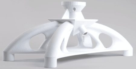
High-reusability PA 12 part 3D printed with MJF 3D Printing technology. Source: HP
Calibrating Connection Points
To validate a design that has gone through 3D printed assembly consolidation, the focus needs to lie on the weakest link in the chain mating to the rest of the mechanical system. General tolerances are an important starting point. But for critical components that involve sealing surfaces for air or fluid, or that nest tightly with other components to reduce vibration, optimizing that fit is a critical step for long-term project success. Because the 3D printed version may also have more or less material depending on the design requirements, the resulting part may very well perform differently when mounted in the final system and under pressure.
The best practice for ensuring a tight fit is to create different scales in the design phase, in all areas like width, height, depth, latches, or overhangs. By considering this in the design phase to plan for proper testing, you can maximize performance improvements. This also removes most of the potential points of failure. The goal is to ensure that key benefits of 3D printed assembly consolidation are not overshadowed by delays in part release. Conversely, if the potential for consolidation is not overshadowed by delays in part release. Conversely, if the potential for performance gains is not likely, or if there is a risk of introducing more defects into the system, then consolidation should be avoided.

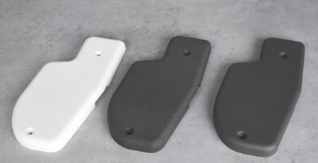
Automotive part 3D printed with PA 12 and MJF 3D printing. Source: HP
Achieving Proper Flow in Medium Delivery
Since 3D printed assembly consolidation is often used to improve performance in liquid and gas systems, flow is another key consideration throughout the design process. The biggest design change is that HP Multi Jet Fusion parts are completely encapsulated in powder at the end of the manufacturing process. This means there would be openings in the design large enough to remove the powder as part of the finishing process. For this reason, one of the key use cases is large routed parts, commonly known as manifolds. Parts that use compressed air are also good candidates for Multi Jet Fusion. Since only the joints typically have higher levels of detail and smaller features, compressed air can be used to clean the channels after manufacturing.
The ability to add complexity to MJF parts at no additional cost also supports the production of parts with specialized flow patterns. You can envision these parts using geometry to create specific vortices or mixing patterns as the gas or liquid passes through the 3D-printed nozzle or conduit. This is particularly interesting for industrial 3D printing because design software for analyzing potential flow, while much more accurate than it was years ago, is still only a predictive tool. 3D printing allows you to produce a variety of designs at little additional cost. In traditional manufacturing, those costs would quickly become so high that the “best guess” or “safe option” becomes the default. The 3D-printed iterations can be tested after manufacturing to see if they meet expectations, underperform, or are runaways for optimal performance. The designs that perform can then be released for higher volume production in the exact quantities needed. Another huge advantage over traditional manufacturing is that if problems arise after use in the field, the design can be changed and incorporated into the next 3D print.
The smoothness of the part is the final major difference between designing for flow with MJF 3D printing and traditional manufacturing. Traditional plastic manufacturing has a smooth surface after milling and polishing the metal mold. Powder-based 3D printing leaves a rough surface, which affects more delicate flow systems by introducing “chaos” into the flow patterns. However, by using the rapid iteration discussed above and testing a few different iterations with each print, one can quickly determine the best design at low cost and high speed. Texturing the 3D printed design can also be used to further improve the performance of the final part.

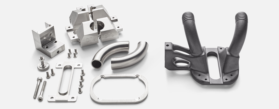
Car defroster vent 3D printed with PA 12 and MJF 3D printing. Source: HP
Relentless Focus on Designing for Function
When designing for additive manufacturing, the final function must be the guiding principle, not the existing assembly design. It is tempting to simply take existing assemblies, close gaps, and print them as a single part because it is quick and easy with 3D printing. While technically possible, this “shortcut” approach usually creates downstream problems. The cost of additive manufacturing is directly related to the amount of material in the part. Failure to optimize volume can quickly result in high unit costs due to the extra material in the design. Other key issues include improper load distribution due to mass concentrations in the design, or elements such as latches and hinges that are prone to breakage because they were not redesigned for the manufacturing process.
These focus areas also deliver more significant cost savings per part and provide a longer-term functional advantage. This DfAM process is more costly in terms of staff time, but it locks in the use case and the customer because the top designs are not easy to replicate, the price per part is optimal, and the functional benefits are significant.
Testing and Release of Consolidated Assemblies
There are five aspects of assembly validation:
- Clear documentation of part specifications
- Targeted testing of function with system components
- Simultaneous testing of multiple designs
- Early initialization of long-term testing
- Clear tracking to manage iteration releases
These quality processes are valuable for individual parts, but they become more important for 3D-printed assembly consolidation because the redesign is much more significant. These guidelines help validate the design before it goes into production or is released into a spare part inventory.

Clear Documentation of Part Specifications
Although the documentation of the part specifications should be a part of every manufacturing process, in many cases it is not given a high priority. In the case of DfAM redesign for assembly consolidation, this is critical during both the design and manufacturing phases. Typically, the design for additive manufacturing (DfAM) process is not performed by the primary project CAD engineer because it requires specialized knowledge that is not widely spread. If the design work is outsourced to a contract manufacturer, they are even further removed from the application. Without clear specifications for critical dimensions within the design and for attachment points, the project can quickly devolve into extensive design iterations and clarification calls.
It is important to remember that 3D-printed assembly consolidation creates a new part. Simply delivering existing drawings is not enough—the CAD designer needs to know what aspects must remain fixed and what features can be adjusted. By understanding these requirements up front, the designer can use best practices to move quickly and efficiently through the design phase.
Documentation is equally important for manufactured parts. Clear specification of the expected result gives the quality assurance team the information they need to properly test the part. 3D printing has been limited to prototyping for so many years, clear documentation has not been a priority. However, production for end-use applications requires that critical dimensions be met every time – and that requires having the information on hand.

Targeted Testing of Function with System Components
Industrial 3D printing is not an anomaly in the manufacturing industry, so the testing and approval process should be based on tried and true processes. In almost every injection molding project, 3-5 parts from the first batch are sent for approval and release to production. This is the same mindset that should be part of additive manufacturing. The first batch of parts should not only be measured against the engineering drawings – they should then be built into the system to check for any remaining concerns. Often, small adjustments are needed (just like in injection molding), which can then be incorporated into the design of the final 3D-printed part.
This step is one of the most likely to be skipped because 3D printing is promoted as the “fastest way to market” in manufacturing. This positions 3D printing as a quick fix. For simple parts that don’t have strict performance requirements, it is often possible to skip additional testing now that the material quality and machine reliability have advanced. (HP has been a leader here with its Multi Jet Fusion technology.) However, more advanced applications, such as 3D printed assembly consolidation, require that extra step of validation. When working with a third-party contract manufacturer, we recommend shipping the mating components to them so that assembly and basic functional testing can be performed onsite immediately after 3D printing. This brings significant speed and efficiency gains to the manufacturing process, as any issues can be addressed directly in the design and added to the next day’s production output.
Simultaneous Testing of Multiple Designs
3D printed assembly consolidation is often about pushing a design to the edge of what is possible to get the best performance benefits. But pushing to the edge can also lead to falling over the cliff. That’s a big problem in conventional manufacturing, where part failure immediately results in long timelines and high costs to remake injection molds, and in the worst cases, can derail entire projects. This (logically) leads conventional manufacturing to take the “safe alternative” to avoid this risk in approaching design.
3D printing offers an alternative. While the adage “complexity is free” is not 100% true, it is inexpensive enough that the benefits of working with multiple designs simultaneously should be exploited to ensure that parts achieve maximum performance. A significant percentage of the value of assembly consolidation comes from exactly these improvements.
In practice, this is accomplished by 3D printing multiple design iterations (typically 3-5) in a single production run for testing and approval. The simplest version of this exercise is to simply scale the entire part so that you have a “tight fit,” a “standard fit,” and a “loose fit” version of the final product. If you are working with assemblies that have critical mating points, you can test the three levels of scaling for each mounting bracket or mounting hole in the part. The most complex level of testing would be to validate the mechanical performance of seal areas or flow patterns within the assembly. Various simulated geometries can be printed and tested in a final system to determine how closely the simulations match the actual performance. The best designs are then given the green light for production.

3D printed glasses printed with PA 12 White and MJF 3D printing. Source: HP
Early Initialization of Long-term Testing
In the military, there is a saying that “two is one, and one is none” meaning without a backup, a plan is worthless. In the case of 3D printing, there is an immediate backup by rapid production of replacement parts in just a few days if needed. But having a “functional” backup is just as important as a physical backup. The design created by 3D printed assembly consolidation should be positioned to push the limits of performance, rather than staying in the “safe middle” of conventional manufacturing. If problems arise, backup parts can be on hand with a simpler, more stable design that will meet the project’s requirements – a “safe middle” version. For a product manager or business owner, this type of de-risking is key to developing innovative products.
The best practice is to take several of the first parts and immediately put them into long-term testing over days or weeks. Since assembly consolidation is typically a replacement for an existing system, taking the time to confirm long-term performance ensures that no surprises will arise in use.
Clear Tracking to Manage Iteration Releases
The final consideration to improve project success is properly managing design changes. 3D printing is unique from other manufacturing technologies in that the best products spring from a more direct collaboration between the designer, the product manager, and the production team. With injection molding, the CAD designer doesn’t need to know what final heat was used to melt the granules or what pressure was used to force the plastic into the mold. With industrial 3D printing, part orientation, and processing have a much more direct impact on the mechanical properties and accuracy of fine details in the final part. This makes communication with the shop floor an iterative process as the design is finalized.
The danger is that during this collaboration, adjustments are made at various points in the chain and aren’t properly incorporated into the final part. For example, the designer may make scale or design changes within small features to improve part fit. The product owner might test different designs that will be produced in a single production run but only make the final decision in a phone call that isn’t stored in a project PLM system. The manufacturing team might make additional adjustments to the feature scale or adjust machine parameters during the manufacturing process to achieve better output. The QA engineer might add special post-processing or finishing to achieve the required dimensional tolerances without updating a process notation. For series production, all of these small decisions must be documented to ensure that the tenth, hundredth, and thousandth parts all reflect the same improvements.
The secret is clear communication and having a lead to manage iterations. In large organizations for standard projects, this would be the product owner. However, they may or may not be familiar with the challenges or potential points of confusion, depending on their experience with additive manufacturing. The advantage of partnering with a 3D printing contract manufacturer is that they are focused on these steps as part of their daily business. The level of documentation is generally higher because they are using processes that have been developed over thousands of customers and decades of 3D printing production.
Capture Success using 3D Printed Assembly Consolidation
For both spare parts and high-performance new products, 3D printing offers a solution for developing a reliable supply of parts at competitive prices.