Designing 3D Printed Parts with Inserts, Threads, and Snap Fits
Over the past five years, there have been significant improvements in the reliability of additive parts. HP has been at the forefront of these advances with its Multi Jet Fusion (MJF) technology, a system designed for high-volume manufacturing of series parts. Both the quality of the material and strength of the bonds between the layers have resulted in mechanical performance that is on par with conventional manufactured parts. Similar performance improvements have been achieved in other plastic additive manufacturing technologies, including DLP, FDM, DLS, and SLA. That reliability has contributed to a broader adoption rate for 3D printing. That led to the next step of integration into full-part assemblies.
This article will outline the three most effective methods for connecting 3D-printed parts to other components, including metal inserts, threaded connections, and snap-fits. Each method has advantages and disadvantages, depending on factors like the required strength, the frequency of reuse, and the placement among surrounding parts. When key factors are accounted for during the Design for Additive Manufacturing (DfAM) phase, 3D-printed components can serve as robust, cost-effective components in a wide range of products and machines.
Metal Inserts: The Industry Standard for 3D Printed Connections
Performing a few checks up front to ensure that the metal inserts will function as expected. 3D-printed parts require sufficient additional material around the connection point to ensure a secure hold. While the exact distance varies depending on the insert size and the type of installation, as a general guideline, we recommend a minimum of twice the inner diameter of the insert as the surrounding material. Therefore, a 1/8″ screw would require a minimum of 1/4″ of material surrounding the hole, with a tolerance range of +/- 1/64″ for the hole’s alignment. Having enough surrounding material is important to ensure the desired level of strength.
It is also important to ensure that all inserts are accessible and correctly placed. Since they are added to the original part by heating and melting them into place, pressing them into the structure, or screwing them in with a counter torque, these areas must be accessible to the finishing team. The resulting connections are robust and able to withstand the wear and tear of daily use.

Brass Inserts
Brass is an ideal material for a range of applications involving hot and cold liquid flow systems. Its heat dissipation capabilities help avoid placing undue stress on the part. Additionally, the material boasts excellent corrosion resistance to salt water, mild alkaloids, and non-oxidizing acids. It is a highly robust material, suitable for deployment in many standard applications.
Steel Inserts
For applications requiring enhanced durability and performance, stainless steel inserts are an excellent alternative. The most significant advantage of stainless steel is its strength, which makes it a suitable material for applications that require high mechanical performance. Additionally, it exhibits superior resistance to aggressive, turbulent saltwater, oil, and acidic environments. It is also well-suited for applications involving food contact, due to its ability to withstand harsh cleaning solutions and advanced surface treatments like chemical smoothing. The cost difference is significant, so steel inserts are always limited to specific performance requirements. However, both stainless steel and brass inserts are compatible with nylon PA 12 MJF parts.
| Insert Type | Considerations for Use |
|---|---|
| Brass Inserts | • Standard applications • Exposure to salt water, alkaloids, or non-oxidizing acids • High accuracy requirements • Cycling of hot/cold |
| Steel Inserts | • High-strength applications • Exposure to moving salt water, oil, aggressive acids, food contact, aggressive cleaning chemicals • High-heat exposure |
Selecting the Proper Metal Insert Design
| Insert Type | Considerations for Use | |
|---|---|---|
| Press-In Inserts (Screw to Expand) | 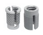 | • Quick installation process • Strength through addition expansion with screw • Highly dependent on hole size • Repeated use or removal of screw can lead to loosening of attachment • Recommended for non-critical applications |
| Press-In Inserts (Hexagon Shape) |  | • Quick installation process • Higher torque strength through hexagonal form • Good pull-out resistance • Highly dependent on hole size • Recommended for non-critical applications with slightly more mechanical stress |
| Self-Threading Inserts | 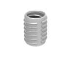 | • Fairly simple installation process • High degree of placement accuracy • Excellent pull-out resistance through outer ridges and cutting directly into part • Moderately dependent on accurate placement of hole size |
| Heat-Staking Inserts | 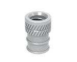 | • Highest overall mechanical performance • Stable over repeated usage • Most complex installation process • Chance of inaccuracy due to tilt during melting • Forgiving of small placement holes but looses stability if placement hole is too large |

When all of these factors are considered in the product design, metal inserts play a crucial role in ensuring that 3D-printed parts perform at a level that matches conventionally manufactured parts.

Adding Functional Threading to 3D Printed Parts
The difference is the underlying strength in today’s 3D printed parts so that the material can be used directly as a mounting point at those threaded locations. The ability to have secure attachment points, without the additional labor and coordination of metal insert sourcing and installation, reduces costs and long lead times. Whether mechanically cut or directly printed, additively manufactured parts with functional threads can be integrated into larger systems with ease, adding value to products and strengthening production streams.
Cutting Threads into 3D Printed Parts
A second method is to mechanically cut the threads into the plastic part. This is done using a pilot hole to guide the location in the part. Then, a drill is used to

cut the hole with threads for the final screw. The advantage is that this is a relatively low labor process and allows a hole to be used more often than with a self-tapping screw. The disadvantage is that it can be difficult to mount the part for effective tapping. Slight tilts in the part can make the final performance problematic. For many parts, we recommend using a jig made with a low-cost 3D printing process such as FDM that includes a negative of the part to effectively “hit the mark” with all of the parts. Alternatively, a tool like Trinckle’s Paramate can be used to make jigs without engineering expertise, to ensure the final production process is simple and repeatable.


Designing Threads for 3D Printing
The advantage of 3D printing threads is that no additional machining is required on the parts. The disadvantage is that the 3D-printed threads produced by MJF must consider the design of round vs. sharp edges. However, if these constraints are considered during the design validation phase, the parts can perform to the standard of other cast parts. Often, 3D-printed parts with pre-designed threads also receive a secondary treatment of infiltration or chemical smoothing so that they are completely air-tight or leak-resistant.
The most common thread applications with 3D printing are for items like caps for industrial cases or pressurized systems with wide, self-locking threads that require a custom fit. This is highly relevant for aftermarket replacement items, spares, or repairs.
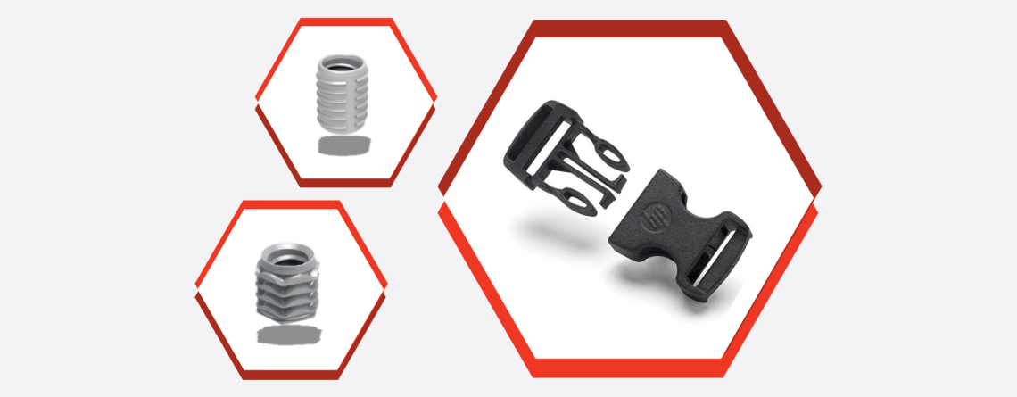
Rapid Assembly using Snap-Fit Union Joints

Snap-fit 3D printed parts have become much more common, due in no small part to Multi Jet Fusion’s popularization of PA11 material. PA11 is much more ductile than traditional PA12, leading to increased use in items such as buckles, cases, covers, electronics, and medical devices. The improvements made to the interlayer strength of MJF also increased the use of snap-fit components, as they can now better withstand counterforces in the Z-direction.
Designing 3D Printed Snap-Fits for Function
The second principle is to round corners and eliminate sharp edges in the parts. These design approaches help ensure long-term function and accuracy by accounting for limitations in the manufacturing process. Rounding corners improves the overall structural strength of 3D printed parts. It is much less likely that localized stress will cause a crack in the plastic if there are no ” focal points”. This is similar to the guidelines for injection molding, but since we are not dealing with milling, where rounding internal shapes happens by default, the rounding should be added to every corner at best.
The third principle is that sharp corners at the top and front of a typical snap fit should also be rounded. This is to ensure strength and guarantee the 1 mm thickness in all areas. By removing sharp edges at the design stage, the engineer ensures proper interaction with the other aspects of the system. Eliminating the front corner where the part is inserted also plays a big role in reducing breakage during assembly, as the snap-fit is more forgiving in “guiding” the element into place. If it is intended to be disassembled later, a similar angle should be placed on the back of the snap to help guide it smoothly back out of the fit.
The fourth principle ensures proper tolerances between the snap-fit and the surrounding elements. Just like a good injection molded design, 3D-printed parts must be designed with a proper fit. A good rule of thumb is to start with the process tolerance of +- 0.2mm. This is also important because a good fit limits the amount of stress placed on the snap-fit during assembly.
The fifth principle applies the same approach of working with the final production engineer to determine the part orientation for the snap fits that will optimize function. As described in the Assembly Consolidation article, unlike other manufacturing processes, 3D printing depends on much more collaboration between manufacturing and engineering to achieve the best results. The basic rule of thumb is to determine the critical tolerance for the functional fit (width, length, or height). Since the X-Z plane provides the highest level of accuracy, the critical dimensions should be placed flat in this orientation. If multiple dimensions are critical, consider an additional round of scaling. The more snap-fit elements that appear on a single part, the more attention must be paid to fit during the initial validation phase. An open dialogue between the production team and the CAD engineer is the best way to adjust design and tolerance expectations on the way to success.
The final principle involves correctly calculating the forces that will be applied to the part to ensure long-term performance. The exact strength depends on the design type (discussed in the section below) as well as the choice of 3D printed material and the function within the final system. However, HP provides a very good overview (Design > Union Joints Design > Snap Fits) that can be referenced for early projects until a good baseline is established.
Selecting the Optimal Snap-Fit Design for 3D Printing
There are different types of snap fits that can be incorporated into the design depending on the function required, the space available within the design, and the frequency of disassembly and reassembly of the fit. We will review the five most common snap-fit types that can be implemented into the system.
| Snap Fit Type | Considerations for Use | |
|---|---|---|
| Cantilever Snap-Fit | 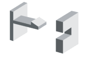 | Selection Criteria: Most common snap-fit type. Cantilever snap-fits are simple to design and provide a robust fit to the matching part. The direct relationship between thickness and connection strength makes it easiest to calculate and adjust. Disadvantage: Pressure is concentrated at base of beam which can be problematic in repeated use. Particularly if there is a short base which limits the elasticity, this can cause breakage. |
| L-Shaped Cantilever Snap-Fit |  | Selection Criteria: When the part geometries don’t allow for enough elasticity/bend then an L-shaped cantilever provides a solution for adding length. The slots to the side are optional but also help increase the flexibility. Disadvantage: Strength is reduced (due to increased length) and is harder to calculate during design phase. |
| U-Shaped Cantilever Snap-Fit | 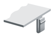 | Selection Criteria: When space is limited or for optical reasons the top surface should not be disturbed, a U-shaped cantilever at the side is a good option. It is extremely flexible and therefore a good solution for items that need to be regularly opened and closed but don’t require much force (like caps and lids). Disadvantage: Strength is again reduced leading to limited applications. |
| Annular Snap-Fit | 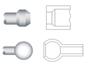 | Selection Criteria: Usually suited for cylindrical or ring-shaped parts (without flat edges) and where the part can be turned into place. Typically strong fit with good alignment of the mating part. Disadvantage: Requires push and/or rotational force to join and remove the connection, not ideal for regular removal. Can be loosened or crack under repeated use. |
| Torsional Snap-Fit | 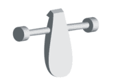 | Selection Criteria: For use as a latch in parts where the release needs to be performed regularly and with a minimum of effort. Can be a strong connection depending on the placement. Rotation access can be 3D printed in place eliminating assembly. Disadvantage: Most intensive to design and ensure proper function. Space and design intensive to ensure the rotation access is well mounted. |
Strong Connections Bring 3D Printed Parts to Industry
With strong connections, the functional performance of 3D-printed parts can match that of traditionally manufactured parts. Using the three connection methods of metal inserts, plastic threads, and snap fits, 3D-printed parts can be smoothly integrated into active industrial systems. There is almost always a way to meet performance requirements with the right design. The guidelines above help ensure a high probability of “quick win” success. Parts that are well designed are critical to developing or maintaining a market advantage, as 3D parts connected to larger systems represent significant cost and time advantages. Now is the time to take advantage of MJF technology and use 3D-printed parts with functional integration through strong connections.