Designing 3D Printed Hinges and Interlocking Components
This article describes the most common methods and design steps for adding motion using 3D-printed hinges or interlocking elements in MJF manufacturing.
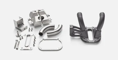
Key Advantages of MJF for 3D Printed Hinges and Joints
- Design complex movements at no additional cost: Because 3D printing doesn’t have the geometry constraints of conventional manufacturing, movements can be controlled and complex. A part can limit the angle of movement, have teeth or burrs lock into place, or increase the resistance of the design during the motion. All features are directly integrated into the 3D-printed plastic.
- Streamline assemblies to take advantage of distributed production: When parts from the MJF machine are fully functional, production can occur anywhere. This is a huge advantage for cross-border production to counter less reliable supply chains and scale-up/scale-down capacity.
- Control motion without additional accessories: Once the powder is removed from the parts, you can have fully interlocked hinges and rotating elements with no additional sourcing or assembly. For more complex components from third-party suppliers, being able to handle production in-house brings big gains in sourcing time.
- Gain part repeatability by eliminating expertise: Parts made with Multi Jet Fusion are repeatable and reliable, no matter where or when they are produced. HP delivers machines built for volume production. These machines deliver production parts. Combine this with the repeatability of eliminating assembly and procurement, and you have a winning combination.

Design Rules for 3D Printing Hinges and Interlocked Elements
Maintaining proper gaps is the key to function
In some cases it may be necessary to work to tighter tolerances. It is possible to produce smaller gaps in certain orientations and use a light force after production to mechanically “snap” the hinge free from thin bonds. However, these tight-tolerance parts are not a guaranteed success, so extra time should be scheduled to 3D print one or more tests. The gap size and print orientation can then be adjusted to achieve a good balance between tightness in the design and repeatability of properly moving parts.
Account for Powder to be Removed
In practice, this means that a 3D-printed hinge or interlocking component cannot be completely enclosed. It must have a slot above or below the joint, or holes at the top and bottom to allow powder to drain out of the part. As a general rule, drain holes should be 3/16″ or larger, which is why gaps are more commonly used to ensure that powder can be removed by air pressure around the hinge point.
Wall Strength
The minimum wall thickness for hinges is the same as the standard design recommendations of 1/32″ in the X-Y direction and 1/16″ in the Z direction. However, since these applications will experience motion and therefore more pressure than a standard wall, it is quite likely that the minimum wall thicknesses will not be sufficient. The more use a hinge will receive, especially if it is moving significant weight, the thicker the surrounding walls should be. Simulation software is an excellent starting point and increasingly covers 3D-printed parts.
Another option is to look at the size and thickness of similar conventionally manufactured components. If you are replacing a metal hinge with a 3D-printed alternative using Multi Jet Fusion, the thicknesses will need to be adjusted to account for the material change. If the design allows, the more the better, as the additional material cost is minor in comparison to the long-term performance benefit.
Overall Dimensional Accuracy

Best Practices for 3D Printed Rotational Hinges
Rod and Pin (2-Dimensional) Rotation
Within a single assembly, different 3D-printed hinges can be produced, allowing movement to occur on different axes within the part. To provide more strength, a part will often have two or three attachment points to the shaft to increase strength during use. It is a similar concept when compared with traditionally manufactured parts, as an individual part will typically have two or three attachment points, just like every door in your home. Because the complexity of 3D printing comes at no extra cost, working with multiple hinges adds strength without adding expense.

3D printing can easily define a limited angle of motion for a hinge by using pins or hard stops to end the rotation. Two basic methods can be used to limit the amount of movement. First, as shown in the image, an extended pin can be placed in a channel so that when it hits the wall, it immediately stops the motion. This is a simple but effective method of defining the range of motion in a component. The advantage is that the connecting pin/clip is usually fairly thick so it can be stopped repeatedly against the wall without breaking. This is similar to how the knee works, where the kneecap provides a hard stop for the leg bone as it moves forward.
The other method is for a pin to extend from the inner rod and control the motion by being blocked within the rotating element. This is a more elegant solution in many ways because the pin is hidden and protected. However, there are a few drawbacks for 3D printing. First, it can be difficult to remove the excess powder in this scenario, so there must be a larger planned gap between the rotating element and the rod. If the gap is too loose, then the movement of the element will tend to “wobble”. This is a balance that must be determined by testing. Second, the pin is by definition smaller because it is inside the rotating element. This means that it has less overall strength and can be more easily snapped if there are higher mechanical pressures on the part.
Ball Joint (3-Dimensional) Rotation
As with the two-dimensional axis examples above, the angle of motion of a ball joint can also be limited by design elements. The same two principles can be applied. First, limiting walls can be added to the master element so that if the extension is too far in a particular direction, then no further movement is possible. This is similar to the shoulder of the body, where the arm has a “hard stop” when it extends to the limit of the tendons connected to it.
For a ball joint, the idea of an internal pin to limit movement can be very effective. Usually pins in ball joints are easier to execute because the powder can be drained from the same gap that allows the general rotation. There is just an additional hollowed-out area in the “cap” where the pin attaches to the rest of the part.
Products with Living Hinges, Flexible Structures and “Fabrics”
The benefits are compelling. Living hinges are an integral part of product design, and the MJF PA11 material in particular, with its high ductility, allows the reproduction of classic part designs without breakage. The flexible ULTRASINT® TPU01 can also be used to produce very resilient living hinges as long as basic design rules are followed.
When creating flexible structures in parts or designing 3D-printed fabrics, movement can happen over an entire surface without complicated manufacturing or assembly processes. The cost savings can be significant. Use cases for parts with flexible structures or fabrics are not as prevalent. However, since advanced DfAM parts tend to compete at the high end of the market, adding these premium features can often be the key to a valid business case. In addition, the tooling for creating flexible structures in standard manufacturing is often expensive. Since this complexity is included for free in 3D printing, this is an area where additive manufacturing can add strong value.

An array of parallel motion living hinges. Source: HP
3D Printing Living Hinges with Hard Materials
The key to success is to adhere closely to the recommended design rules for living hinges, which have been developed over many years for injection molding.
- The hinge needs a certain minimum thickness to ensure repeated performance. For 3D printing, generally, 0.5 – 0.7 mm is recommended to get a clear print and enough powder mass to have the expected performance. The minimum thickness includes multiple layers of material bonded by the MJF process.
- Parts should be printed with the living hinge perpendicular to the X-Y plane to maximize the hinge strength. The flat plane is exposed in a single pass to fuse the material. This gives strong bonds in this direction and is similar to the added strength in injection molding when the living hinge is in the same flow direction as the material.
- A radius should be added to the outside of the bend and an option to add a dent in the middle where the hinge folds. These two tricks help to reduce the stress on the hinge when it bends. Adding the radius between the thin and thick material reduces the possibility of tearing along sharp corners. Removing a line of material at the bend point as a “V” or “U” shape reduces the pressure at that main fold.
Unfortunately, 3D printing still doesn’t provide the same consistent material strength as injection molding, especially where bending stresses are placed repeatedly on the part. Even when following the guidelines above, the fact that 3D printed parts are bound together by individual particles rather than a molten mass of material like injection molding makes the performance less rather than a molten mass of material like injection molding makes the performance less robust and not suitable for continuous use over long periods.

PA 11 foldable clip. Source: HP
Because we strive for a balance of thin material (for good motion) and thick functional areas (for robustness in use), final physical testing is the key to success. Living hinges that are 3D printed can be made in multiple designs and thicknesses in one batch, so testing and validation of those various designs can occur immediately. The best design in terms of usability and durability can then be released for production. Improved resolution and better material properties to support bonding between layers have made 3D-printed hinges a more common part of end-use products.
Flexible, Functional Living Hinges using 3D Printing
Chemically smoothing TPU parts improves visual surface quality and seals the rough surface into a single, stronger layer. Like rounding the corners between the thin and thick parts, chemical smoothing removes the sharp “powder edges”, making them less tear-resistant and therefore much more durable over time. Chemical smoothing also increases the resistance to water, dirt and other contaminants to improve the reliability and robustness of the final parts.
3D Printed Fabrics and Moldable Forms


Adding Value to Parts with 3D Printed Hinges
- Complex motion can be incorporated into parts at no additional cost.
- Distributed production of parts across multiple facilities around the world or with trusted manufacturing partners is possible and easy because all functionality is included in a single design.
- Accessories like hinges or brackets are eliminated, so you are not dependent on third-party delivery schedules, and you can adjust design and performance with a simple CAD design change that you control.
- Single-source procurement for spare parts is especially important for items that may be needed 10 to 15 years down the road, or for low-volume production of specialty components. It eliminates the need to manage assembly documentation or maintain a backlog of subcomponents.
For many decades, 3D-printed components from a single source have been a clear goal. Advances in manufacturing quality, material performance, and the development of a clear design language make these parts attainable. The design advantages of 3D-printed hinges, long used in injection molding, are now being added to parts in industrial applications around the world.