Additive manufacturing with Multi Jet Fusion is a direct alternative to conventional manufacturing. The strength, performance and reliability of industrial 3D printing meet the rigorous demands of applications across all industries. With this wider adoption has come a growing interest from end users, from entry-level engineers to seasoned product managers,
in the principles that guide the way to the best results.Similar to injection molding, designing good 3D printed parts requires balancing accuracy and aesthetics. We call these principles MJF DfAM (Design for Additive Manufacturing). By making key decisions up front, success is ensured downstream. Unlike our previous posts on basic guidelines of DfAM and advanced DfAM business cases, here we will compare the trade-offs between aesthetics and accuracy. Each of these topics is a choice to be made based on the project requirements. The results will ensure a part that delivers the best possible results based on sound MJF DfAM principles:
- Part Orientation
- Print Parameters
- Rounding Corners
- Wall Thickness
- Placement Tolerances
- Mass Ratios
- Lattice Structures
- Surface Texture
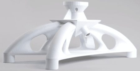
The biggest influence on surface quality and accuracy in Multi Jet Fusion 3D printing is print orientation. Therefore, this should always be the first decision in MJF DfAM. The top side of the part is cured as a single layer during production. This makes it the most accurate, as the binding ink is deposited directly on the top. It also has the cleanest surface, as long as it is flat, because no other powder touches that surface during curing. While an ideal part may have only one critical surface that the production engineer can orient upward, the reality is that many sides can often be expected to have accuracy and clean surfaces. The challenge then becomes choosing an orientation that balances the two requirements.
HP Multi Jet Fusion Process. Source: HP
The opposite happens at the uneven locations between the cured “blocks” of powder. These blocks are called
voxels – the 3D printing equivalent of a pixel on a screen. Because they are small, edged blocks, they have visible corners after production. This leads to visual lines in the part when the angle of the corners becomes visible in
an effect called ‘stepping’. It is most visible on flat or low curvature areas (see image below). The MJF DfAM recommendation is to tilt the entire part so that low-angle planes are sharp angles to minimize the stepping effect.
Ideal MJF printing angle. Source: HP
The voxels can also affect accuracy in the Z direction. There are two factors at play. First, in the case of a hole or letter oriented in the Z direction, the machine is printing new layers on powder rather than fused material. While HP maintains the best possible accuracy in that plane, because the powder is loose, it will sometimes be a little lower, sometimes a little higher, and this will result in discrepancies in the part or inaccuracy for tight tolerances in the Z-axis. In particular, it is difficult to achieve perfect roundness of the hole in the Z-plane, and it usually has to be corrected by scaling that feature of the part.
By orienting the most critical plane upwards, you can ensure the best results on that plane for text, tight tolerance holes, pins or critical threaded elements.If you have two or more critical planes around the part, it is often best to orient the entire part so that each face is 30° or 45° to the top of the machine. This will cause some distortion on each side, but it will be minimal and should be the same distortion on each side. When working with an external service provider, they will often be able to see the part and scale from experience to get the best results.
The other primary effect of part orientation is the “down-face,” the side of the part that faces toward the bottom of the machine. The down-face has the opposite effect of the up-face in terms of aesthetics since it is completely lying on uncured powder. But the down-face has the same accuracy because it is on the X-Y plane and the print heads can directly apply the binding ink. If your part has a clear “back”, this is an ideal scenario. If there is no clear front and back, this may also be a reason to go more for the 45° orientation approach. Some designers like the aesthetics of the back for certain parts, it is a rougher but interesting surface texture. It also tends to have more randomness to it because of the slight irregularities in how the powder is applied. The texture can be compared to the noise texture in injection molding. In that case, “the bug would become a feature”.
In summary, print orientation is the first and most critical decision to be made when balancing accuracy and aesthetics. Choosing the placement of the up, down, and z-axis faces directly affects the surface texture, placement accuracy, and roundness of certain features such as holes, text, and pins. Alternatively, the part can be angled at 30° or 45° to have a more uniform effect on part accuracy and surface texture across the part when there is no “primary face”.
Placing the Right Emphasis
The next major lever available to influence the balance between accuracy and aesthetics is the production material and printer settings. While this may seem mundane, it is often overlooked that selecting the
technical print mode can be the difference that brings a 10-20% increase in performance or the
fast print mode can add the 10-20% speed increase that is the profit margin of the project. As shown in the graphs below for PA11 material, the mechanical print mode dramatically increases elongation and impact strength as well as surface and color quality, but at the expense of dimensional accuracy and speed. This needs to be a deliberate choice at the beginning of the project that is communicated to the production engineers. This will not only help them to choose the right combination from HP’s pre-defined settings and materials, but will also help them to optimize during production. Experience also plays a big role here. Small adjustments to print speed or the amount of binder used can provide those same 10-20% improvements to produce the best parts. Working with
a trusted production partner when that experience is not within your team pays off.
The choice of print material is equally important to the final result of the project. Each material has its advantages and will skew the result more towards aesthetic or accurate parts.
PA12 is always looked at as the baseline material because it was the first material to be widely available for industrial 3D printing. It provides a good balance of strength, surface finish and performance within the part.
PA12 GB (Glass-bead reinforced plastic) actually has a better surface finish and color distribution in addition to the increased tensile strength from the reinforcement in the plastic. However, this less flexible material also has a tendency to warp, so dimensional accuracy is sacrificed, especially if there are large flat and relatively thin areas in the part. But for parts that are structural housings – this is an ideal switch from PA12 because you get both the better optical surface and the protective strength. Another key advantage is that PA12 GB also has higher heat stability.
PA11 covers a similar range of applications to PA12, but with improved surface quality, surface uniformity and elongation. At first glance, this almost always leads to a decision for a PA11 material in a head-to-head comparison. However, PA11 doesn’t perform as well in the higher temperature ranges that are quickly reached in outdoor applications. In addition, the material is always more expensive to purchase and print, sometimes as much as 1.5 to 2 times, because there are not the same volumes driving the economics.
The second way to balance aesthetics, accuracy, performance, and business case is to make clear decisions at the beginning of the project about the basic print setting and material. The best approach is always to focus on the critical feature. By communicating this to the production team, they can select the appropriate settings and further optimize them during the production process.
Fillets Add Strength and Durability
The next factor that affects the aesthetics and accuracy of parts is designing fillets into parts. This differs from the first two aspects because
adding fillets to corners and edges improves both aspects of 3D printed parts.
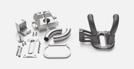
From an accuracy and performance standpoint, fillets serve the important function of reducing stress concentrations within the part. It is a simple concept; just like the corners of tables that are most likely to catch your leg as you walk by in your house, sharp edges in a part also catch the main impact. The more rounded a corner is, the more the stress will roll off that corner and soften the impact. This can be as simple as adding a fillet rounding of 3/64″ (1mm) to all edges and corners within the part. For the downward facing areas of the part, it is often recommended to add chamfers between 1/64″ – 1/32″ (0.3 – 0.5 mm) to improve aesthetics. Because the downward face rests directly on powder, the flat angle gives a better result than rounding
In the photo of the parts above, you can see that the parts have a mixture of rounded and unrounded elements. The top part has only a slight fillet on the sharp edges for the mating surfaces where a tight seal must be made into an existing system. Those are not a problem, especially since they will be fixed in place to a metal component. The rule of thumb is to
add fillets wherever design limitations allow to improve the overall performance.
The part on the bottom right has only a slight fillet on all of the crossbeams. Because the goal here is lightweighting, they wanted to minimize the use of material and not go in the direction of more organic shapes with higher structural strength. There is much more material at the attachment points, and the corners are clearly rounded to eliminate the possible “stress points” within the part where the main pressure will occur.
Fillets also provide important aesthetic benefits. In 3D printing (as in injection molding), a more uniform distribution of material improves the surface quality and accuracy of the final part. MJF 3D printing is a thermal process, which means the material is heated and cooled together. The more uniform the mass distribution in the design, the better the surface quality. This also helps to eliminate surface imperfections that can result from a thicker base cooling faster than a thin wall above it.
Corners are particularly vulnerable because when walls are thin, they tend to warp as they cool (as we will learn in the next section). The fillets at the base and also vertically within the part help to distribute these “cooling forces” more evenly and maintain the overall integrity, accuracy and visual beauty of the part. The aesthetics are different from an injection molded part, where a cleanly milled sharp edge is the quickest way to a part. Rounded corners and edges provide important benefits to the aesthetics and accuracy of 3D printed parts.
Balancing Wall Thickness with Strength
Thin, precise and strong walls are a sign of quality in plastic parts. Compared to injection molding, 3D printed parts need to have slightly thicker walls to achieve similar strength, and they can never be as thin. For
HP MultiJet Fusion parts, using 1/32″ (0.6 mm) as the minimum wall thickness will ensure successful 3D printing, which we discussed in detail in our
basics of design for additive manufacturing (DfAM). Because of this, we recommend being conservative with wall thickness in your 3D printed parts and designing thicker than necessary to ensure the integrity of the bonded material.
Thick walls are also generally more problematic in 3D printing than in injection molding. In injection molding, the material is heated all at once, then forced into metal form and immediately cooled; distortion (warping) can occur if areas of the part are too thick relative to the rest of the design, but it is controllable and usually affects the fit of the part but not the structural integrity. In 3D printing, the part is constantly heated and cooled slightly before the next layer of powder is added. This means that warping during printing makes additive manufactured parts much more susceptible to structural defects, from waviness (orange peel effect) to small stress fractures, due to small separations between layers as the parts are built up. Depending on the placement in the printer during production, this can also occur in different areas of the part. Then, when the final cooling process occurs at the end of production, there are similar effects to injection molding of warping, where the thicker areas pull into the part and the thinner areas push out. The solution, described in our
Advanced Design for Additive Manufacturing (DfAM) post, uses lightweighting principles to maintain part strength and avoid the pitfalls of thick walls.
Internal helmet lattice. Source: HP
For lattice parts (interlocking networks of thin beams), it is even more critical to work with sufficient thickness. For most tactile lattices, the closer the 3D printed part is to a fabric, the more our body recognizes it as visually and tactilely familiar. This is achieved with thinner walls and smaller cells. However, the aesthetic and tactile advantage is “paid for” with more difficult cleaning, critical QA testing for breakage during production, and challenges to long-term performance. The denser the lattice, the more difficult it is to completely clean the part. Removing the powder requires higher air pressure, longer cleaning cycles, or even mechanical pounding to loosen the powder – all of which can damage the lattice structures. Lattices produced at the minimum wall thickness (1/32″) or less mean that even a small imperfection can ruin an entire part. Aiming for healthy wall thicknesses of 1/32″ or greater is the best practice for producing stable and high-performing lattice parts.
The Quest for a Tight Fit
Determining the proper spacing and tolerances for covers, gaps, and holes is the next big decision that every additive manufacturing designer faces when trying to balance mechanical performance with aesthetic appearance. By its nature, industrial 3D printing has a wider tolerance range than injection molding. In HP Multi Jet Fusion, the print head applies new powder and then a binder to the powdered surface. When the print bed is heated, these bond to create a strong and accurate, repeatable part. However, the variability in powder distribution and the accuracy of the binder application still
limits MJF to a minimum tolerance of 1/64″ (+/- 0.3 mm). In contrast,
injection molding, which places the molten plastic into a metal mold, has a standard tolerance of 1/192″ (+/- 0.1 mm) and can achieve tolerances approaching 1/384″ (+/- 0.05 mm) for fine part applications. This is important to consider in the design phase, especially when mating plastic with metal parts.
To achieve the best balance between aesthetics and technical performance in 3D printing, there are two main “levers” (1): orienting critical technical areas upwards (see first section) and designing according to common behaviors of 3D printed parts. Proper tolerances provide users with the aesthetics of a good fit for lids, accurate placement of screw holes, and smooth motion when parts are mated. When the CAD engineer considers the standard behavior of additive manufactured parts during design, the results will be at the tightest rather than the widest end of the tolerance spectrum.
Here are the main “behaviors” to be mindful of:
- Holes tend to be smaller than designed
- Thicker areas and walls tend to shrink during cooling
- Edges will tend to warp if not rounded
- Openings on the Z-axis will tend to be slightly shorter than designed
- Tapered joints will be more accurate than sharp corners
These basic tendencies can be accounted for with standard scaling factors during the design and proper preparation for printing. An external print service will usually take this into account automatically in their production process. Otherwise, these are the issues that need the most attention, and perhaps even a test part, when preparing for a larger production run. The goal is a tight fit that provides the aesthetics of a well-designed part. For mating parts, the best rule of thumb is to design the plastic inner part to the larger end of the tolerances, as it will tend to shrink, and the outer/cover part to the smaller end, as it will tend to warp slightly outward. The MJF software will adjust somewhat for “oval” holes, but those are also key to scale or test so that they remain round and large enough, especially when mating with metal components. That can be a short checklist to verify each new design prior to the final release for production.
The Power of a Smooth Transition
One of the most underrated ways to improve both the accuracy and visual appeal of Multi Jet Fusion parts is to ensure smooth transitions of material throughout the part design. This is quite similar in many ways to injection molding, where there is an understanding of maintaining uniform wall thickness throughout the part. This is important so that the material flow is uniform and gets into all the corners of the part. In industrial 3D printing, localized, uniform wall thickness is also important for good quality parts. This helps ensure similar shrinkage profiles and consistent heat distribution during manufacturing.
This is important for individual parts, but also for the distribution of parts within the production machine. Having a similar amount of mass per production layer and evenly distributed across the X-Y plane helps improve part accuracy and part surface quality. There are several software tools available, both directly from HP and from third-party vendors such as
Materialise or
Oqton, that can automatically create this distribution in the build job.
This is also where industrial 3D printing has the ability to produce a different subset of parts than what is produced in conventional manufacturing. Smooth transitions between different amounts of mass within the part can still result in parts that are both technically accurate and aesthetically clean. When discussing
Design for Additive Manufacturing, this is the biggest mindset and approach shift.
Smooth transitions can be made within a part with the gradual addition of mass so that heat and shrinkage are still controlled during the manufacturing process. The key then is to balance that with maintaining a good distribution in the printing process, such as flipping the part 180° so that the overall distribution of mass remains balanced within the print chamber. The more uniform the transition, the better the production result. For large parts, it is possible to simply increase the amount of mass within the part for strength, but over the course of the design. It is important to note that the more mass, the more heat is generated and retained in the part.
To improve accuracy and minimize distortion, the largest mass group should be high up in the build job. This will allow the heat to build up steadily during printing and then be stopped near the end of production.
This also applies to individual components. Injection molding, which relies on CNC-milled metal molds, tends to have hard edges and sharp corners. These are the easiest to design and execute when translated into CNC machine code. Industrial 3D printing builds parts layer by layer. When the plastic particles being bonded are attached securely on two sides instead of just one, it creates a much stronger part. You can think of it as holding on with both arms, where it is easy to maintain a stable position and shift your weight from side to side. The whole system is stable. Designing with fillets or rounding in 3D printing allows each point to bond strongly on each side and have that same improved strength.
By creating uniform mass transitions within parts and within build jobs, heat is better managed, and surface area of bonding is increased for better part quality. Controlling these factors also improves production accuracy and ensures better surfaces. When there is an abrupt transition from thick to thin, the thin part will shrink faster and create a visual marring, usually as a line on the outside showing where the mass is inside. This can also happen with thicker parts in an MJF build, especially with dense packing. Only with smooth transitions can you maintain visually clean surfaces and optimize for aesthetics.
When Lattices are Worth the Effort
The use of lattices in the context of wall thickness and improving part accuracy was described above. This is a critical area for improving engineering part accuracy by using lightweight approaches to eliminate warpage. Lattices also have clear performance advantages to influence design aesthetics and “dial in” accurate mechanical performance in functional applications.
First, the design aesthetics of lattice parts for users are mostly related to flexible lattices from the TPU materials. Unlike a traditional foam, 3D printed lattices (1) offer breathability through the “air” in the latticed parts, (2) give the design freedom to mix open and closed areas and (3) use different cell shapes and densities for specific feelings of the user. The open design, which adds airflow into the system,m is a direct benefit that justifies the extra cost for many end-users, especially when considering how many hours per week or year the helmet is used. The aesthetics are further improved by mixing open and closed areas within the design. This is also unique to additive manufacturing. Closed areas to touch the skin and create a tight seal at critical locations. The lattice can then compress and cushion as needed for the application. Depending on the required mechanical demands, or in the case of individualization even directly to the user preferences. These are all aspects that justify Multi Jet Fusion applications, especially for industrial applications or long-term usage scenarios.
3D printed headrest. Source: HP
Second, lattices in both hard and soft parts allow flexibility to adjust the lattice parameters and directly affect the mechanical performance of the resulting part. This is much more difficult with solid walls in conventional parts. An additively manufactured component can be designed with certain “compression areas” using lattices between solid walls. Different thicknesses can be used throughout the part and there is freedom to transition between open and closed sections as well as complex shapes. The parameters of these parts can then be adjusted to quickly or produce in various strengths as part or initial testing to dial in the exact mechanical strength needed for the final part. Industrial 3D printing also provides an option to produce solid walls with a lattice center to maintain both flexibility and strength in a single component.
Ankle foot orthoses printed with PA 11. Source: HP
Adding proper lattices to additive parts requires a different skill set from the CAD engineer and product designer, as described in our
advanced design for additive manufacturing. However, when the right balance of lattice design and performance is achieved, parts will perform at a higher level than is possible with traditional manufacturing. Those companies that find the product gaps and lock in unique applications can find a protected niche with scalable and accurate HP Multi Jet Fusion production.
Surfaces are the First Impression
The final decision in balancing technical accuracy and aesthetic quality is part finish. As mentioned in the O Orienting on Top Results above, there is a clear trade-off between part orientation, technical accuracy and surface quality. In terms of engineering precision for sizing and roundness, all objects in the X-Y plane are significantly more accurate than those tilted at an angle or along the Z axis. In addition, the upward facing surface is also where the best results are obtained. This should always define the critical orientation.
Surface finish is also more directly affected by part orientation. Depending on the part shape and part requirements, it may be necessary to sacrifice accuracy for surface quality.
Car mirror 3D printed with PA 12. Source: HP
Here are also a few simple guidelines to follow:
1) Flat surfaces printed flat will be clean.
2) Flat surfaces that are slightly sloped will have a stair-step effect.
3) Slightly curved surfaces printed flat will also show a stair-step effect.
4) Once the angle exceeds 15°, stair-stepping is no longer an issue.
If the part is going to be used in visible applications (not as an engineering part), then avoiding the clear signs of 3D printing, such as stair-stepping, can greatly help adoption rates. 3D printing is still a young technology that has had quality and consistency issues in the past. Making the production process less visible helps users to judge purely on performance. This is where HP’s Multi Jet Fusion technology is setting a new standard for scalable, reliable production. In the years to come, the marks of 3D printing may even be a source of quality, but for now, adjusting part orientation to follow the 15° rule will go a long way toward improving part surface quality.
Optimizing Accuracy and Aesthetics remains a Balancing Act
3D printed parts that balance these seven principles will get the best possible results from Multi Jet Fusion manufacturing. For most fast-paced companies, even investing the engineering time to redesign for additive manufacturing (MJF DfAM) can be a hurdle. But this initial investment pays off. Using these guidelines to make decisions can make the process faster and more efficient.
Working with an outside service provider can also provide valuable feedback to ensure the right balance between accuracy and aesthetics.
3D printed parts are becoming an increasingly important part of complex machinery and for maintaining a flexible supply chain for many leading companies. The HP MJF process is an excellent choice because it is designed specifically for high-volume manufacturing. 3D printing often requires a trade-off between accuracy and aesthetics during the design process. But when done consciously and by following the guidelines in this checklist, the results provide long-term value with unique and high-performing plastic parts.


 (2)")